






Semih Asil
Industry Valley
- Thread Author
- #1
A Scenario on the Factory Floor 🏭
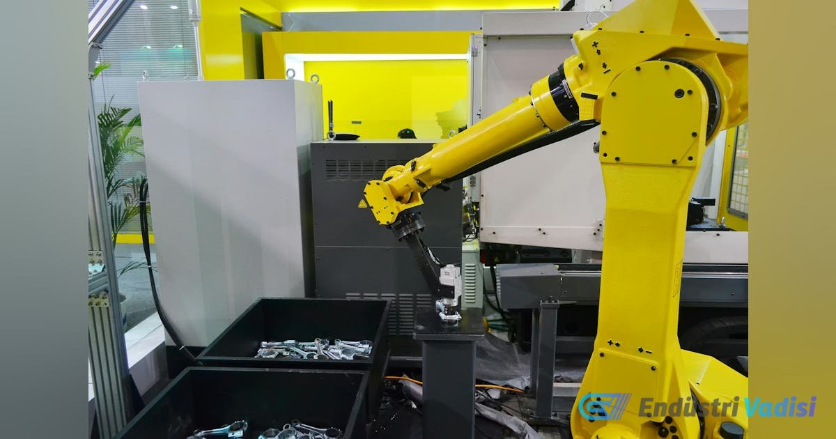
Imagine a factory. Next to a robotic work cell, a digital monitor displays a live view of a deep bin filled with randomly placed mechanical components. As a new bin arrives, the machine vision software quickly initiates an inference process. On the screen, the target object is identified and isolated with high statistical probability. Yet, the six-axis robotic arm in the physical work cell remains motionless; the robot, it seems, still lacks the information needed to move. This operational gap highlights one of the most significant inconsistencies in modern machine building: object detection is the preliminary output of a robot-vision system, not its ultimate goal. To bridge this gap, engineering teams must examine strategic decisions focusing on spatial calibration, deep sensor integration, rigid trust rules, and adaptive mechanical execution.
Customer Needs and Machine Vision 🎯
Customers want to feed components into a line with less sorting, manipulation, and orientation before the machine takes over. This requirement has shaped our investment in machine vision. The machine should handle parts as they arrive, and the customer should spend less time preparing each part for a rigid vision setup.
Detection Produces an Image Result, Not Robot Instruction 🖼️
To design a reliable automated production line, engineers must separate the abstract milestones of computer vision and mechanical movements. In an industrial workflow, translating raw camera data into physical actions requires a progressive translation process. This process can be broken down into four main stages: classifying an object, locating it within an image, estimating its position and orientation in physical space, and generating an executable command.
- Classification: Treats the image as a single data point. It can be highly effective for basic sorting or simple quality checks but provides no spatial context.
- Object Detection: Builds upon classification by identifying the target and mapping its location within a 2D pixel grid. The software draws a bounding box around the component or creates a pixel-level segmentation mask.
- Projection into 3D Physical Space: To become valuable for machine building, 2D pixel coordinates must be mathematically projected into 3D physical space. The automation architecture must calculate the component's exact position and orientation relative to a defined coordinate origin through Six Degrees of Freedom (6DoF) tracking: position with precise spatial coordinates (X, Y, and Z) measured in millimeters, and orientation with angular rotation (roll, pitch, and yaw) relative to the sensor or workspace.
- Robot Command Generation: To create a safe, executable robot path from these 3D coordinates, the system must feed these physical targets into the robot controller's kinematic engine, which calculates joint angles, motor positions, and optimal paths.
Calibration: Connecting Vision to Action 🔗
Industrial environments are highly dynamic, challenging spaces, and mechanical setups do not remain static over time. With environmental variables constantly at play, automation teams must stop viewing calibration as a static, one-time task completed during initial commissioning. Instead, calibration should be treated as an integrated, active subsystem within the live production environment.
This can be achieved using automated Tool Center Point estimation routines. By programming the robot to periodically present its tool or a specific calibration target to the camera at predefined intervals, such as after shift changes or a certain number of cycles, the system can automatically account for and adjust any physical drift. Treating calibration as a continuous operational protocol ensures the long-term reliability of the work cell and guarantees that the vision-to-action translation remains accurate over months and years of continuous operation.
Depth Transforms Perceived Shape into a Physical Target 📏
Consider a complex, real-world manufacturing scenario, such as a bin-picking application where hundreds of industrial screws are randomly dumped into a deep bin. In this environment, a 2D vision system is fundamentally inadequate; a flat image cannot determine if a screw is on top of the pile or buried at the bottom, nor can it distinguish between a large screw resting deep within the bin and a smaller one resting just beneath the lens. The automation system must combine 2D intelligence with 3D physical data by pairing specialized deep learning vision models with advanced 3D depth sensors, such as structured light cameras or time-of-flight sensors.
This hybrid approach executes a clear, multi-step engineering workflow to transform a flat shape into a tangible physical target. First, isolate the component through segmentation masks that distinguish the object from its background. Then, the system overlays this 2D pixel mask onto the real-time depth map generated by the 3D sensor. In the screw bin example, combining the 2D mask with 3D depth data allows the software to analyze sudden height changes at the edge of a part, determining which screw is resting on top and which parts are buried underneath. Once an unobstructed screw is selected, the system analyzes the clustered 3D points within that part's specific segmentation mask. This step maps a true physical object occupying a specific volume in space, calculating the object's precise orientation and physical surface topology. Finally, the automation software evaluates the calculated surface topology to select an optimal gripping point. For a robotic arm equipped with a magnetic or mechanical gripper, the system must find a flat, stable surface area on the head or body of the screw. This step also verifies that the robot's physical jaws or magnetic tool can cleanly grasp the target without colliding with adjacent, overlapping screws or the rigid walls of the bin.
Trust Must Influence Machine Behavior ⚖️
An industrial vision model operates entirely on probabilities rather than absolute certainties. When a deep learning algorithm identifies a part, it assigns a mathematical confidence score; for example, there is a 94% probability that the perceived shape matches the target component. However, there is no single confidence threshold that works for every industrial application. The acceptable level of mathematical certainty is strictly determined by the process, the component, and the financial or safety consequences of a failure.
When a vision system encounters an ambiguous detection, the machine should not guess. Instead, the automation logic should execute a defined stop condition or an automated recovery routine. For instance, in an advanced bin-picking environment, if a component is highly obscured by another part, the system might calculate a low confidence score. Rather than risking a blind grasp that could damage the tool, the controller should trigger a non-destructive recovery action. If a secondary scan still fails to meet the confidence threshold, the system should execute a controlled shutdown of that specific station, preventing a cascading shutdown of the entire assembly line.
When a machine vision system pauses or requests engineering validation, the human-machine interface must communicate effectively with the floor operator. Showing an operator raw bounding boxes, tensor dimensions, or cryptic software error codes is unhelpful and increases downtime. Instead, the system should present clear, actionable diagnostics, such as visually highlighting problematic areas, providing plain-language status messages instead of software error logs, and offering guided solutions like "rescan the bin" or "authorize manual grasp." By designing clear trust rules and intuitive interfaces, manufacturers ensure that machine learning remains reliable.