


Hasan S. Cemkan
Corporate
- Thread Author
- #1

A practical look at how 2NO/2NC contactors and auxiliary contacts simplify command, feedback, and fault logic in motor circuits.
When commissioning a new conveyor line, the forward/reverse starter looked technically sound. The PLC sent a forward command, the run light illuminated, and the HMI reported the motor as healthy. However, the drum on site never moved. The contactor coil sounded like it was trying to pull in, the overload protection was untouched, and the electrician was looking for a problem that should have passed the FAT test.
Similar problems can be seen in overhead cranes, HVAC condenser fans, and small packaging conveyors: Status points indicate the motor is running when it's actually stopped, or a required interlock silently fails. While the details vary, the fundamental problem recurs wherever simple starters and forward/reverse contactors are used.
This article is prepared for control and automation engineers who design forward/reverse starters or HVAC motor starters and then support them during commissioning and service.
Our focus is on the clear separation of command, status signals, and fault monitoring functions through the conscious use of 2NO/2NC auxiliary contact blocks.
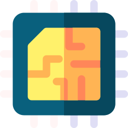
### 2NO/2NC Contactor Example
(Figure 1) DIN-rail mounted 4-pole (2NO/2NC) contactor device and schematic.
### Fundamental Problems
Ambiguous situations prevail in many motor control problems. The coil might be energized, but it's unknown whether the main contacts have closed, if the mechanism is jammed, or if a welded contact is hiding a "normal" status in the background.
In many panels, auxiliary contacts are used simply "because they are there." An unused NO powers a RUN pilot lamp, an NC gets mixed into the permissive chain, and the same contact tries to serve as both a seal-in and a status signal. There is usually no written documentation indicating which signal is for command, which represents actual contact movement, and which is for interlocking.
Result: Run indicators reflect the coil command, not the contact status; interlocks rely on the wrong contact, and PLC tags use "ContactorIn" when they actually mean "CoilCommand." The system cannot provide clear information in a fault condition, even when there is no short circuit or open circuit.
### Motor Coil and Contact Movement
When the coil is energized, the armature moves. Both main and auxiliary contacts change state: Normally open contacts close, and normally closed contacts open. This electrical movement means power is applied to the motor and the indicator changes from STOP to RUN.
However, in practice, schematics deviate from actual wiring, spare contacts can be re-purposed during commissioning, and the functional meaning of each NO/NC contact is not recorded in a single place. The lack of a common definition for states makes it difficult to understand forward/reverse starters during a fault.
### Functions of 2NO/2NC Auxiliary Blocks
These blocks should be considered as separate tools with four distinct functions. This structure mechanically provides two NO and two NC contacts linked to the same coil movement. This is usually sufficient to separate command, feedback, and interlocking functions.
- Electrical interlocking in a forward/reverse set is generally done by wiring the NC auxiliary contact of one starter in series with the coil of the other. Thus, when the forward coil pulls in, the forward_interlock_reverse opens the circuit and prevents the reverse coil from pulling in. Mechanical interlocking, as a separate safety measure, physically prevents both contactors from closing simultaneously.
- The remaining contacts are used to separate command and feedback signals.

### Simple State Table
A table is used to define how the command and feedback signals should behave under normal and fault conditions for each combination. This ensures that ladder logic is based on a clear specification rather than just "looking right."
### Recommendations for Using 2NO/2NC Auxiliary Contactors
- Command signal (e.g., FWD_CMD)
- Run feedback (FWD_RUN_FB)
- Drop feedback (FWD_DROP_FB)
- Electrical interlock (FWD_INTERLOCK_REV)
Signals that should occur with the energization of the coil and movement of the contacts are clearly separated in this way.
### Fault Scenarios and Proposed Solutions
If the PLC does not receive feedback from contact movement despite the coil being energized, this means "command present but no movement." In such cases, an alarm should be raised, and the technician should check coil voltage, upstream permissives, and mechanical movement.
If the PLC sees a false RUN signal, reverse operation should not be initiated, and it should warn "forward contactor feedback stuck." In this situation, the main contacts and auxiliary block should be measured to check for contact welding or mechanical sticking.
Incorrect wiring of the auxiliary contactor (e.g., NO instead of NC) or not wiring it at all are also common problems.
### Hardware Selection and Schematic Notes
2NO/2NC contact combinations are particularly important in compact contactors, especially in HVAC and small industrial panels. Wiring and function names (like FWD_RUN_FB, FWD_DROP_FB) should be written on the circuit diagram; generic names like "Aux1," "Aux2" should not be used.
### Pre-Commissioning Check
A small check before energizing a new motor starter can save a lot of time.
### Conclusion
When field problems arise, clear signal names and a simple state table make troubleshooting easy. It's possible to quickly determine which signal, coil circuit, or auxiliary block is at fault.
The use of 2NO/2NC auxiliary contact blocks as four defined tools, rather than just as spares for an empty contact, should be designed to give them clear roles in control, status indication, and interlocking. This reduces false RUN indicators in HVAC and small industrial motor applications and speeds up FAT and commissioning processes.
Provides support for up to 20A current in power and signal lines for EMI suppression.