




Semih Asil
Industry Valley
- Thread Author
- #1
Improving Safety and Efficiency in Underground Mining
In underground mining and tunneling, geotechnical stability relies on the integrity of installed ground support systems. Rock reinforcement elements such as friction bolts, mechanically anchored bolts, and grouted tendons stabilize the rock mass by securing loose strata and controlling convergence around openings. Geotechnical engineers face significant challenges when evaluating installed reinforcement: physical inspection under unsupported or newly blasted ground exposes personnel to environmental hazards, while manual measurement of bolt patterns across extensive tunnel networks creates measurement discrepancies, slow documentation, and high operational costs.
xCell Vision: Automated Ground Support Quality Control
Sandvik has introduced xCell Vision, a cloud-based software platform designed to automate rock bolt identification and validation processes. Operating as an extension of Sandvik's Digital Ground Support Platform, this system transforms raw spatial measurements into validated geotechnical installation metrics. By replacing subjective manual inspection with systematic, algorithm-driven assessments, engineering teams can pinpoint out-of-specification installations and prioritize physical inspections only where anomalous ground reinforcement patterns occur.
LiDAR Point Cloud Processing Architecture
The software's core architecture processes 3D point cloud data derived from multiple underground mobile and fixed measurement configurations. The data ingestion pipeline supports point clouds captured by the following methods:
- Handheld mobile mapping scanners used during routine geology walk-throughs
- Tripod-mounted fixed laser scanners used for high-density geotechnical investigations
- Machine-mounted scanning systems integrated directly onto production drill rigs, bolting equipment, or auxiliary haulage fleets
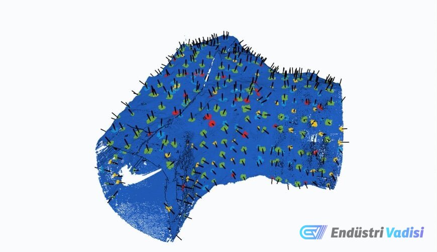
Once spatial point clouds are uploaded to the cloud environment, machine learning classification models segment individual reinforcement elements from rough, shotcrete-lined, or fractured rock mass geometries. The model detects different bolt types, filters out background surface irregularities, and calculates vector orientations within the scanned excavation profile.
Automated Geotechnical Parameter Extraction
The platform automates the extraction and quantitative assessment of four key geometric parameters:
- Total bolt count: Verifies the total installed reinforcement within predefined excavation intervals against design.
- Bolt spacing: Calculates the spatial distance between adjacent collar locations to confirm adherence to approved geotechnical bolting grids and ring spacing.
- Bolt orientation: Measures the 3D insertion angle and vector trajectory relative to the excavation profile and expected local joint sets.
- Exposed tail length: Quantifies the length of steel extending beyond the collar and face plate, validating proper anchorage depth and plate contact.
The extracted parameters generate an interactive 3D digital model of the scanned underground infrastructure. Within this spatial viewer, geotechnical engineers can compare physical installations against planned support design standards, visually isolate substandard bolting densities, and export analytical datasets directly into broader mine planning and ground control records.
Improving Operational Safety and Planning
Eliminating direct manual tape measurements and physical collar counts in active work areas reduces measurement personnel exposure to unsupported ground, vehicle interaction hazards, and airborne particulates. From an engineering workflow perspective, automated spatial processing redirects geotechnical human resources toward high-level risk assessment and reinforcement optimization rather than repetitive data collection.
Additional Information
Digital quality assurance for rock reinforcement forms an expanding discipline within digital mining operations. In traditional underground workflows, QA/QC inspections followed industry guidelines defined by international rock mechanics associations (e.g., ISRM) and national mine safety regulators, which mandated regular verification of support installation compliance against approved Ground Support Management Plans (GSMP). Historically, compliance audits relied on paper checklists, mechanical pull tests on a small percentage of bolts, and manual tape and inclinometer surveys.
Automated analysis tools are evolving in conjunction with modern terrestrial and mobile LiDAR technology. Comparable approaches in the geotechnical and tunneling inspection sector include specialized point cloud processing packages from software providers such as Deswik, Maptek, and Bentley Systems, and mobile scanning OEM analytics such as those paired with Emesent Hovermap systems. While general mining software packages often require manual point cloud classification or custom CAD scripting to extract individual bolt vectors, dedicated machine learning models aim for near-instantaneous automated segmentation of small-scale hardware elements from noisy underground environments.
Standard terrestrial LiDAR hardware typically provides range accuracy within 2 to 6 millimeters, whereas SLAM-based (Simultaneous Localization and Mapping) mobile units generally capture point clouds with accuracy ranging from 10 to 30 millimeters, depending on trajectory drift and scanning speed. Automated bolt identification software must accommodate these resolution differences, recognizing bolt plates and protruding threaded tails, which are often less than 100 millimeters in total dimension, against irregular shotcrete surfaces. As underground mobile machinery increasingly incorporates real-time LiDAR payloads, automated analytical platforms are shifting from post-survey desktop assessments toward closed-loop automated validation directly following the bolting cycle.