




- Thread Author
- #1
In manufacturing plants, conveyor systems play a crucial role in transporting raw materials, semi-finished products, and finished goods between production stages. To ensure smooth conveyor operation, soft starting, and flexible speed adjustment, many enterprises use variable frequency drives (VFDs / inverters) to control the motors.
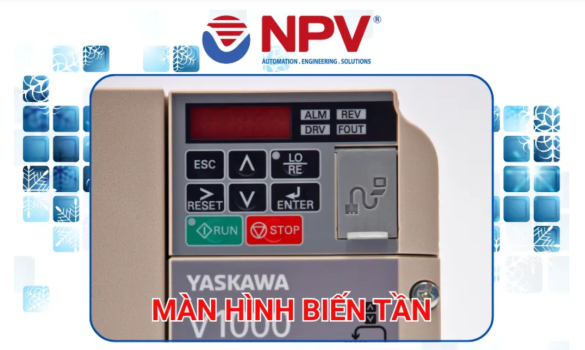
The Yaskawa V1000 is a versatile drive suitable for various industrial transmission applications, including conveyors. However, configuration must be based on motor capacity, load characteristics, mechanical drive mechanisms, and actual operating requirements. Improper settings can lead to starting difficulties, overcurrent, sudden stops, or unstable conveyor speeds.
This article provides a step-by-step guide to setting up the Yaskawa V1000 inverter for industrial conveyor systems, covering everything from verifying motor parameters to setting run commands, frequency references, and protective functions.
Industrial conveyors typically feature relatively steady load characteristics once running, but require sufficient starting torque to overcome initial static friction and move the material. Depending on the design, systems may use PVC belts, roller conveyors, chain conveyors, or heavy-duty belts.
The Yaskawa V1000 supports multiple motor control methods, including:
Before configuring the Yaskawa V1000, inspect the motor nameplate and cross-reference it with the drive's output specifications.
Key information to identify includes:
For three-phase asynchronous motors, entering the correct rated current is critical, specifically parameter E2-01. Parameters related to motor characteristics and the V/f curve must also be configured according to the nameplate and selected control mode.
One notable feature of the Yaskawa V1000 is the Application Presets function, which allows quick setup of predefined parameter groups tailored to specific applications.
For conveyor systems, the target parameter is A1-06 (Application Presets).
According to the Yaskawa V1000 technical manual, available settings include:
These preset values are references provided by Yaskawa and are not mandatory for every conveyor system. In particular, the 3-second acceleration and deceleration times are default recommendations. For long, heavily loaded conveyors or systems with high inertia, these values must be adjusted to fit actual operating conditions.
On the Yaskawa V1000, the primary parameters are:
For conveyor systems:
Technicians should start with the preset baseline and fine-tune during no-load and full-load trial runs. If rapid stopping is required, evaluate the system's braking capabilities and consider installing a suitable braking resistor as specified in the drive manual. Never arbitrarily shorten deceleration time beyond mechanical safety limits.
Once motor parameters and ramp times are configured, select the appropriate control method for the conveyor system.
The Yaskawa V1000 can receive commands from the digital operator keypad, external control terminals, or network communications.
Key parameters to configure include:
During operation, fault codes may occur due to improper parameter configuration, mechanical overload, or unstable power supply.
When a fault occurs, record the fault code and investigate the root cause before resetting. Repeatedly resetting faults without resolving the root cause can cause permanent damage to the motor, drive, or conveyor mechanism.
While the built-in Conveyor Application Preset helps streamline setup, technician verification through no-load and full-load commissioning remains essential to ensure stable, reliable, and safe long-term operation.
The Yaskawa V1000 is a versatile drive suitable for various industrial transmission applications, including conveyors. However, configuration must be based on motor capacity, load characteristics, mechanical drive mechanisms, and actual operating requirements. Improper settings can lead to starting difficulties, overcurrent, sudden stops, or unstable conveyor speeds.
This article provides a step-by-step guide to setting up the Yaskawa V1000 inverter for industrial conveyor systems, covering everything from verifying motor parameters to setting run commands, frequency references, and protective functions.
1. Selecting the Right Control Mode for the Conveyor
Industrial conveyors typically feature relatively steady load characteristics once running, but require sufficient starting torque to overcome initial static friction and move the material. Depending on the design, systems may use PVC belts, roller conveyors, chain conveyors, or heavy-duty belts.The Yaskawa V1000 supports multiple motor control methods, including:
- V/f Control: Suitable for general-purpose drive applications with relatively simple configuration.
- Open Loop Vector Control (OLV): Ideal when the system requires better torque and speed control, especially under fluctuating load conditions. This mode requires entering exact motor parameters and performing an Auto-Tuning procedure according to the manual.
2. Verifying Motor Parameters Before Setup
Before configuring the Yaskawa V1000, inspect the motor nameplate and cross-reference it with the drive's output specifications.Key information to identify includes:
| Parameter | Inspection Content |
| Power | Rated motor output power (kW / HP) |
| Voltage | Rated voltage (V) |
| Current | Rated current (A) |
| Frequency | Rated frequency (Hz) |
| Speed | Rated speed (r/min or RPM) |
| Wiring Connection | Star (Y) or Delta ($\Delta$) based on rated voltage |
Important Note: The rated motor current must be within the drive's output current capability. When selecting equipment, do not rely solely on kW rating; always check current capacity, duty ratings (Heavy Duty vs. Normal Duty), and overload capabilities.
3. Utilizing the Conveyor Application Preset Function
One notable feature of the Yaskawa V1000 is the Application Presets function, which allows quick setup of predefined parameter groups tailored to specific applications.For conveyor systems, the target parameter is A1-06 (Application Presets).
According to the Yaskawa V1000 technical manual, available settings include:
- A1-06 = 0: General-purpose (no application preset).
- A1-06 = 2: Conveyor Application.
| Parameter | Function | Value in Preset Configuration |
| A1-02 | Control Method Selection | 0 – V/f Control |
| C1-01 | Acceleration Time 1 | 3.0 seconds |
| C1-02 | Deceleration Time 1 | 3.0 seconds |
| C6-01 | Drive Duty Rating | 0 – Heavy Duty (HD) |
| L3-04 | Stall Prevention During Deceleration | 1 – Enabled |
Acceleration and deceleration times directly impact conveyor performance.Safety Warning: Changing A1-06 may automatically alter multi-function input/output terminal configurations. Always verify control signal terminals and interlock logic before performing initial test runs.4. Setting Acceleration and Deceleration Times
On the Yaskawa V1000, the primary parameters are:
- C1-01: Acceleration Time 1
- C1-02: Deceleration Time 1
For conveyor systems:
- Too short acceleration time: Requires excessive starting torque, leading to high current spikes and triggering overcurrent protection (OC).
- Too long acceleration time: May fail to meet production line speed requirements.
Technicians should start with the preset baseline and fine-tune during no-load and full-load trial runs. If rapid stopping is required, evaluate the system's braking capabilities and consider installing a suitable braking resistor as specified in the drive manual. Never arbitrarily shorten deceleration time beyond mechanical safety limits.
5. Setting Run Command and Frequency Reference Sources
Once motor parameters and ramp times are configured, select the appropriate control method for the conveyor system.The Yaskawa V1000 can receive commands from the digital operator keypad, external control terminals, or network communications.
Control via External Terminals
When using pushbuttons, selector switches, or PLC digital outputs, configure the RUN command source for terminal control. Set parameter b1-02 = 1 (Control Circuit Terminal).Speed Control via External Potentiometer
To adjust conveyor speed using a physical potentiometer, connect it to analog input A1 according to the manufacturer's wiring diagram. Set the frequency reference source parameter b1-01 = 1 (Analog Input Terminal) and verify analog scaling parameters if necessary.Control via PLC Communication
If the PLC controls the conveyor via Modbus RTU (RS-485), configure the H5 parameter group and set both the run command (b1-02 = 2) and frequency reference (b1-01 = 2) to Serial Communication. Register addresses and scaling factors must be cross-checked with the MEMOBUS/Modbus manual for the V1000.6. Configuring Protective Functions for Conveyor Systems
Conveyors often run continuously in harsh industrial environments. Proper protective settings are essential to prevent motor and mechanical drive damage.Key parameters to configure include:
- E2-01: Set the motor rated current to enable accurate thermal overload protection.
- L1-01: Motor Overload Protection Selection.
- L3-04: Stall Prevention During Deceleration.
- C1-01 & C1-02: Proper ramp-up and ramp-down times.
- E1-04: Maximum Output Frequency limit based on motor and mechanical constraints.
7. Commissioning and Test Run Procedure
After completing configuration, follow a systematic testing procedure:Step 1: Wiring & Installation Inspection
Verify power input, motor connections, grounding, control inputs, and protective devices. Ensure there are no phase wiring errors or loose terminal connections.Step 2: No-Load Motor Test
Run the motor at a low frequency to check rotation direction. If the motor rotates in reverse, stop the system and resolve the wiring according to technical procedures. Never swap wiring while the inverter is still energized.Step 3: Acceleration & Speed Ramp Test
Gradually increase the frequency target while monitoring current draw, motor speed, noise, and vibration levels. If current spikes abnormally, inspect the mechanical assembly and parameter settings.Step 4: Full-Load Testing
Load material onto the conveyor and observe performance during startup, continuous transport, acceleration, and deceleration. Check for torque hesitation or warning flags on the drive keypad.Step 5: Safety Stop & Interlock Verification
Test emergency stop buttons, sensor signals, fault stopping behaviors, and production line interlocks. Only put the system into official operation after all safety checks pass.
8. Troubleshooting Common Yaskawa V1000 Conveyor Faults
During operation, fault codes may occur due to improper parameter configuration, mechanical overload, or unstable power supply.| Fault Code / Symptom | Possible Cause | Recommended Action |
| OC (Overcurrent) | Excessive load, acceleration time too short, short circuit on output | Check motor, cables, and mechanical load; increase acceleration time (C1-01). |
| OV (Overvoltage) | Deceleration time too short, high load inertia | Increase deceleration time (C1-02) or install a braking resistor. |
| oL1 (Motor Overload) | Motor operating above rating or incorrect E2-01 setting | Check mechanical load, actual current, and verify E2-01 value. |
| OH (Overheat) | High ambient temperature, blocked ventilation, fan failure | Check cooling fan, clear heatsink air passages, and check panel enclosure cooling. |
| Motor Does Not Run | Incorrect run command source, active interlock/fault, missing enable signal | Check b1-02 setting, input signal status, and active fault logs. |
9. Conclusion
Configuring the Yaskawa V1000 inverter for industrial conveyor systems requires careful alignment between motor nameplate data, load dynamics, and operational requirements. Essential steps include selecting the appropriate control mode, programming motor data, configuring acceleration/deceleration ramps, assigning control sources, and enabling protection limits.While the built-in Conveyor Application Preset helps streamline setup, technician verification through no-load and full-load commissioning remains essential to ensure stable, reliable, and safe long-term operation.